MultiMode Heater/Cooler Setup
- Verify that the Thermal Applications Controller (TAC) is set to the appropriate voltage configuration for the regional power supply (see Figure 1).
CAUTION: Do not obstruct the ventilation slots of the Thermal Applications Controller.
- Set the TAC power switch to Off.
- Plug the power cord into the rear panel of the TAC and into the power supply.
- Connect one end of the 9-pin connector into the Serial Port on the back of the TAC and the other into one of the COM ports of the computer.
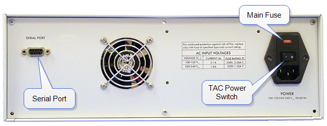
Figure 1: Thermal Applications Controller (Rear Panel)
- Verify that the power disconnect device is readily accessible.
- Set the TAC power switch to On (see Figure 1), and verify that the controller has power.
- If you are installing a 60°C heater element ("BioHeater"), skip to Installation of the 60°C Heater Element.
- Install the Dimension Icon base springs. See Figure 2.
Figure 2: MultiMode with Heater/Cooler Components Connected
- Place the manifold ring on the Dimension Icon base with the cables and connectors on the left side as shown in Figure 2. Tighten the two set screws to secure it to the Dimension Icon base with the supplied 5/64" Allen wrench (hex key).
- Mount the scanner to the Dimension Icon base:
- Route the scanner cable and silicone tubes through the opening in the base.
- Secure the scanner mechanically with the stabilizing screw.
- Plug the 9-pin cable of the scanner into the 9-pin receptacle on the Dimension Icon base.
- Plug the 7-pin Lemo connector on the cable from the scanner base into the 7-pin receptacle on the manifold ring (see Figure 2).
- Plug the 7-pin Lemo connector on the scanner extension cable, attached to the manifold ring, into the 7-pin Scanner receptacle on the front panel of the TAC (see Figure 3).
- Connect the tip heater cable to the 4-pin Lemo connector labeled Tip Heater on the front panel of the TAC, shown in Figure 3. Connect the other end of the cable between the Dimension Icon head cable and the corresponding base receptacle (see Figure 4).
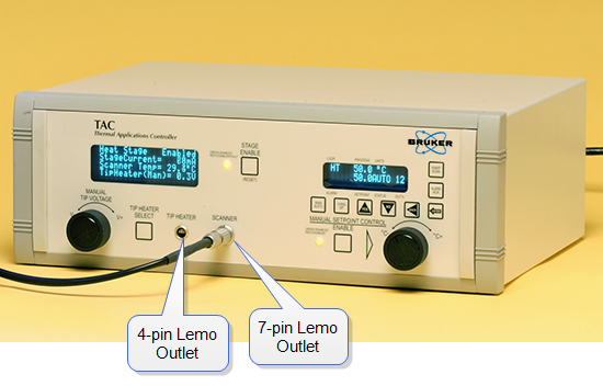
Figure 3: Thermal Applications Controller (Front Panel)
Figure 4: Inline Adapter: Dimension Icon Base to Head Cable
| www.bruker.com
|
Bruker Corporation |
| www.brukerafmprobes.com
|
112 Robin Hill Rd. |
| nanoscaleworld.bruker-axs.com/nanoscaleworld/
|
Santa Barbara, CA 93117 |
| |
|
| |
Customer Support: (800) 873-9750 |
| |
Copyright 2010, 2011. All Rights Reserved. |
Open topic with navigation